 / Build guides
ATtiny85 chip programmer built from spare parts
Build the spare-parts ATtiny85 programmer from Episode 02 on a breadboard or perfboard - schematic, wiring, and bench checks before you burn your first sketch via Arduino as ISP.
Parts list
- Arduino Nano (or Uno)
- ATtiny85 (8-pin DIP)
- Breadboard or perfboard (prototype board)
- 10 µF electrolytic capacitor
- 470 Ω resistor
- 5 mm LED (any colour)
- Slide switch
- Male-to-male jumper wires
- USB cable for the Nano
The build, in 4 steps
Before you start
This programmer is built from parts you probably already have: an Arduino Nano (or Uno), an ATtiny85, and a handful of passives. Build it on a breadboard, or solder it onto perfboard if you want to keep it.
Once it's built, head to the Arduino as ISP guide to set up the software and flash your chip.
Circuit diagram
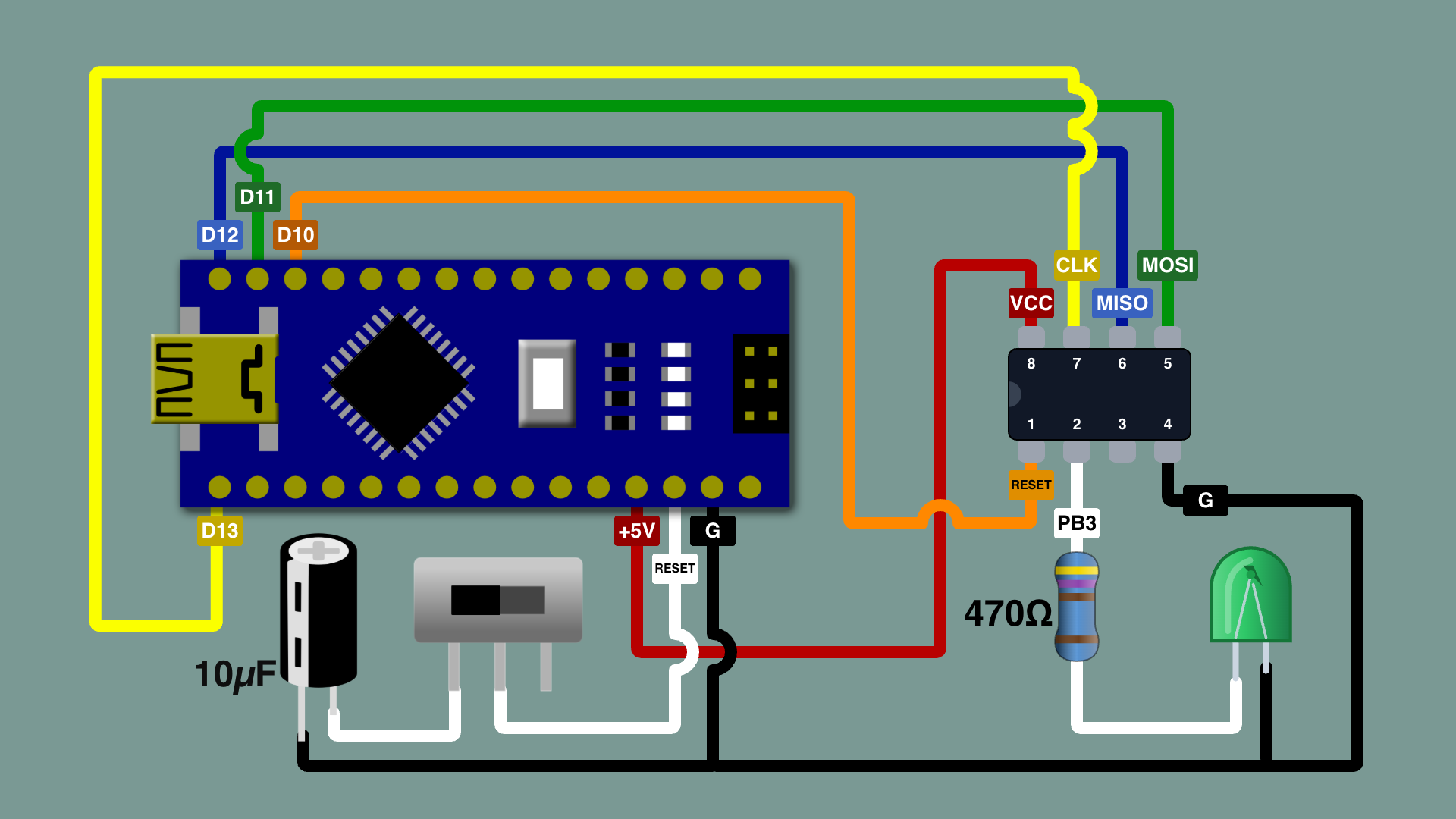
Wire it to match the diagram: Nano on the left, ATtiny85 on the right, shared ground along the bottom. On perfboard the connections are the same, just keep the ISP wires short.
The coloured wires are the ISP link. The LED on PB3 is optional, but handy for a first Blink.
ISP and power
Connect the Nano to the ATtiny85:
| Nano | ATtiny85 pin | Signal |
|---|---|---|
| D10 | 1 | RESET |
| D11 | 5 | MOSI |
| D12 | 6 | MISO |
| D13 | 7 | SCK |
| 5V | 8 | VCC |
| GND | 4 | GND |
The Nano powers the ATtiny from its 5V pin, so you don't need a separate supply.
Reset cap and switch
Programming the ATtiny needs the Nano's auto-reset turned off. Uploading to the Nano itself needs it on. The cap and slide switch let you flip between the two.
- Wire the slide switch from the Nano RESET pin to the 10 µF capacitor.
- Wire the capacitor's other leg to GND. The striped (negative) leg goes to GND.
- Switch on: the cap is connected. Use this when uploading to the ATtiny.
- Switch off: the cap is disconnected. Use this when uploading the ArduinoISP sketch to the Nano.
For the optional LED, wire a 470 Ω resistor from ATtiny pin 2 (PB3) to the LED's long leg, then the short leg to GND.
Bench check
Before you upload:
- The Nano has the ArduinoISP sketch on it (see the IDE guide), and the switch is on.
- Every wire matches the diagram, with no swapped MOSI and MISO.
- ATtiny pin 1 (RESET) is wired to D10 and isn't left floating.
Then run Upload Using Programmer from the IDE guide. If you added the LED, use PIN_PB3 in your sketch to blink it. That's physical pin 2.