 Project Colin
/ Build guides
Project Colin
/ Build guides
LED chaser light circuit - using ATtiny85
Knight-rider LED chase on a Digispark ATtiny85. Circuit diagram, downloadable PDF, and the sketch — with a link to the Apple Silicon upload fix if you have not done that yet.
Downloads
Parts list
- Digispark ATtiny85 board
- 74HC595 8-bit shift register (DIP-16)
- ULN2803A Darlington array (DIP-18)
- 5 mm LED (any colour)
- 330 Ω resistor (¼ W)
- 0.1 µF ceramic capacitor (100 nF / 104)
- Breadboard
- 5V power supply
- Male-to-male jumper wires
- USB cable or hub (USB-C Mac)
The build, in 3 steps
Before you start
This build uses a Digispark ATtiny85 on Apple Silicon. If you have not already fixed the board package and uploader, work through the Digispark setup guide first — uploads will fail without it.
Gather everything in the parts list above before you start. The circuit uses three ICs on a breadboard: the Digispark drives a 74HC595 shift register, which in turn drives eight LEDs through a ULN2803A Darlington array.
Circuit diagram
Wire the LED chaser to match the diagram. A printable PDF is in the downloads panel above.
The ATtiny85 only has three free GPIO pins, so the 74HC595 expands those into eight outputs. The ULN2803A sinks current for the LEDs — the shift register cannot drive them directly.
↓ attiny85-led-chaser.pdf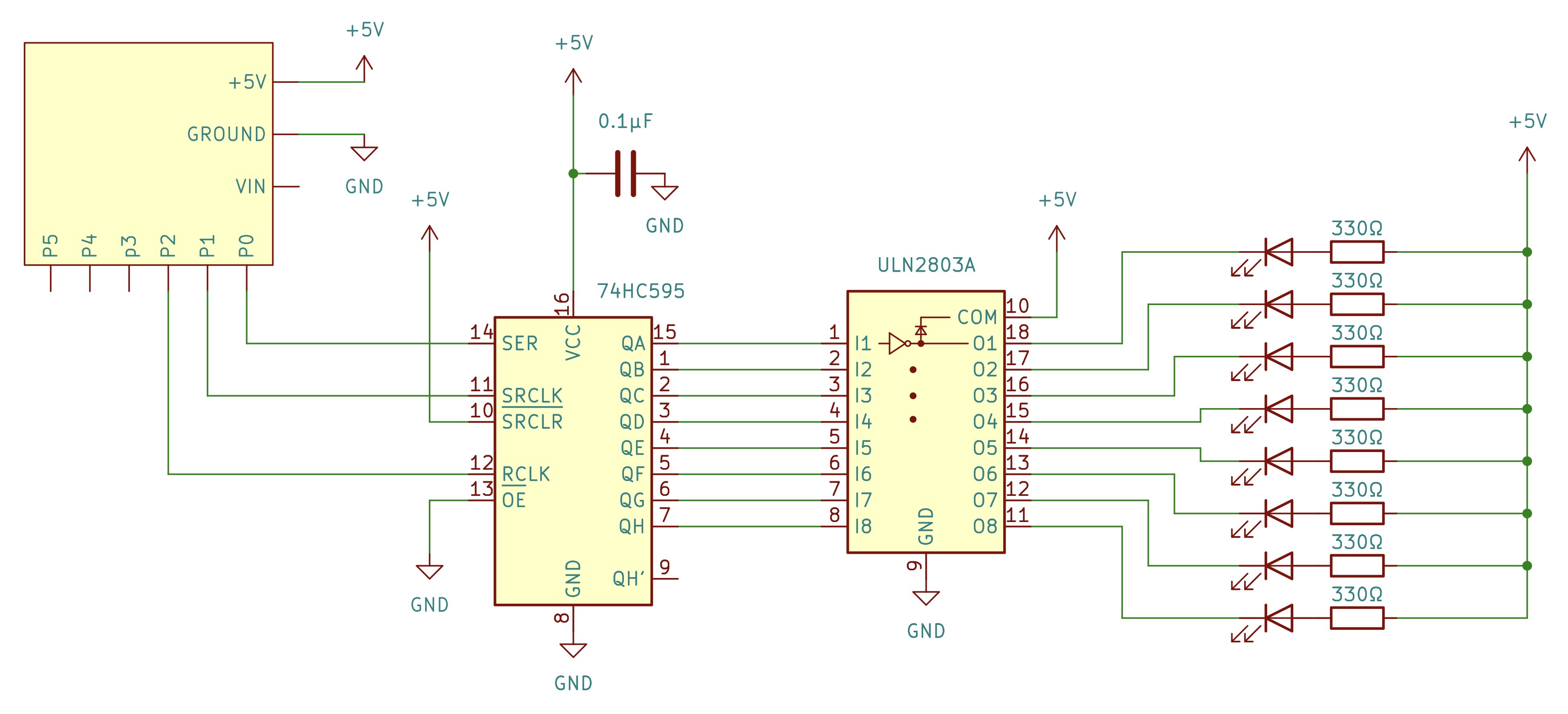
Write the sketch
Copy and paste this code into the Arduino IDE for the version used in the video.
cpp// Pin mappings on ATtiny85
const int dataPin  = 0;  // PB0 -> SER   (Pin 14 on 74HC595)
const int clockPin = 1;  // PB1 -> SRCLK (Pin 11 on 74HC595)
const int latchPin = 2;  // PB2 -> RCLK  (Pin 12 on 74HC595)

const int stepDelay = 80;    // Milliseconds between steps
const int pauseDelay = 1000; // 1-second pause at the end of the sweep

void updateShiftRegister(byte leds) {
  digitalWrite(latchPin, LOW);
  shiftOut(dataPin, clockPin, MSBFIRST, leds);
  digitalWrite(latchPin, HIGH);
}

void setup() {
  pinMode(dataPin, OUTPUT);
  pinMode(clockPin, OUTPUT);
  pinMode(latchPin, OUTPUT);

  // Clear outputs initially
  updateShiftRegister(0x00);
}

void loop() {
  // 1. Forward sweep: LED 0 to LED 7
  for (int i = 0; i < 8; i++) {
    updateShiftRegister(1 << i);
    delay(stepDelay);
  }

  // 2. Return sweep: LED 6 down to LED 1 (avoids double-hit on ends)
  for (int i = 6; i > 0; i--) {
    updateShiftRegister(1 << i);
    delay(stepDelay);
  }

  // 3. Turn off all LEDs and pause before repeating
  updateShiftRegister(0x00);
  delay(pauseDelay);
}
Uploading procedure
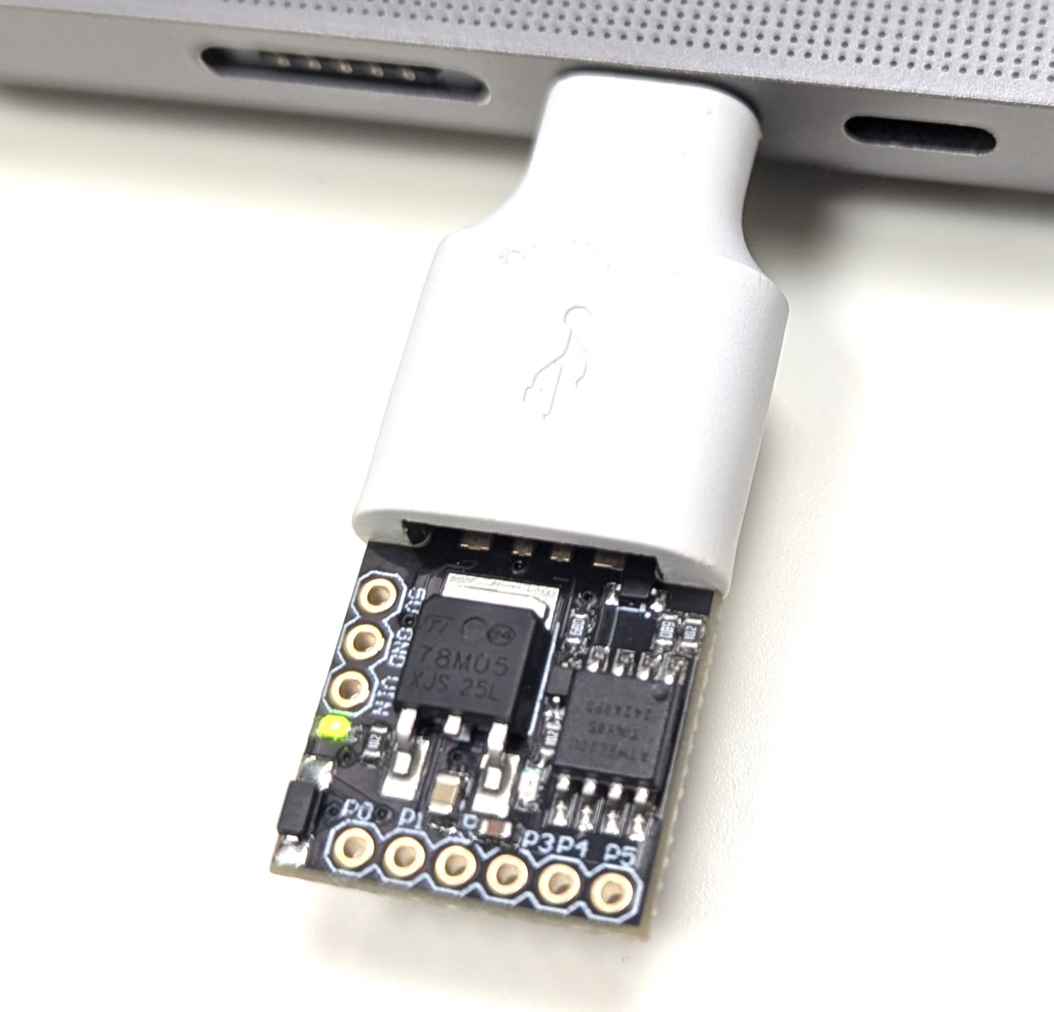
Before you carry on make sure that you have setup the Arduino IDE with the Digistump boards package. A full guide to doing this can be found here
Ensure the Digispark is unplugged from your Mac's USB port.
If your Mac only has USB-C ports, you will need a USB hub or adapter to connect the Digispark.Click Upload in the Arduino IDE.
Watch the console until you see:
text
Running Digispark Uploader... Plug in device now... (will timeout in 60 seconds)Plug the Digispark in. The bootloader connects and finishes the upload within about 5 seconds.
Error opening bus 002 device 001: Device not configured. That is usually harmless — it often clears on its own after a few seconds. If it does not, unplug the Digispark and plug it back in; that should clear it.